Breadcrumb Trail
Bailey-Bridge - Models
OpenSCAD models and STL's
Downloadable Bailey Bridge Models/Component Part Models for: 'Original' (SBB); Standard-Widened (SWB); M1; M2; Extra-Widened (EWBB) & Mabey/Acrow
| Description | OpenSCAD model | STL Files | Images / Renders | Other Files |
|---|---|---|---|---|
|
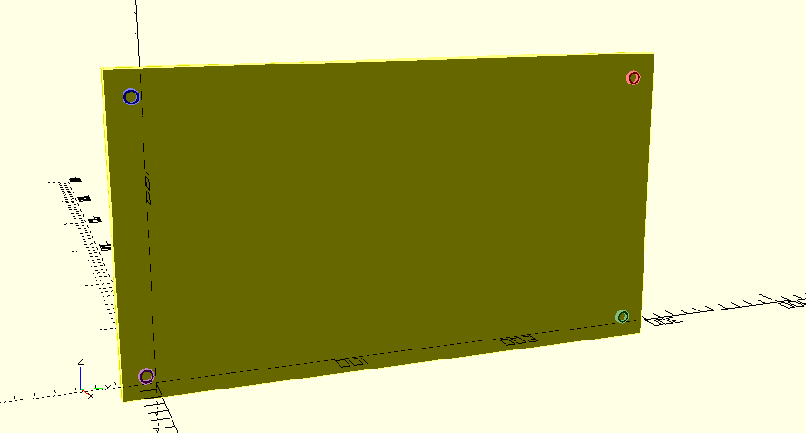
Base-Plate - One is used at each corner of a typical bridge.
Used to aid in layout, and to spread the load to prevent the bridge sinking into the ground. Full model - OpenSCAD format |
|
|||
|
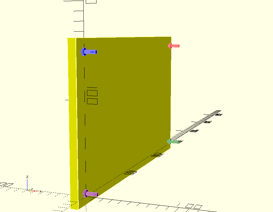
Modified Base-Plate.
The flat plate forming the bottom has been removed, as it is difficult to print the visible upper surface smoothly. Cut a pice of plastic to fit (and glue in place,) for a better result. |
||||
|
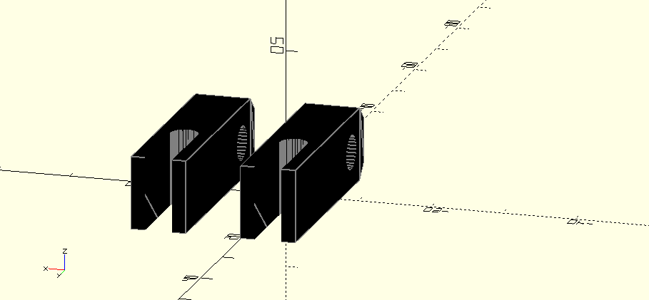
Construction Bearing. At least four needed per bridge. Allows the bridge to flex slightly, as needed.
Full Model |
|
|||
|
Modified Construction Bearing. At least four needed per bridge. Allows the bridge to flex slightly, as needed.
Shafts removed for easier printing. Fit rods of an appropriate size and material after printing. |
||||
|
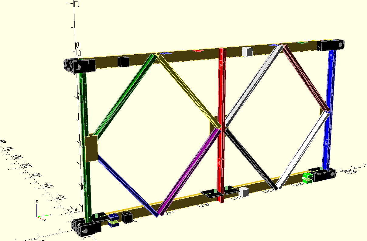
Standard Bailey Bridge Panel
Common to most Bridge versions. Full panel, with central lifting hole - not present on all bridge versions. |
|
|||
|
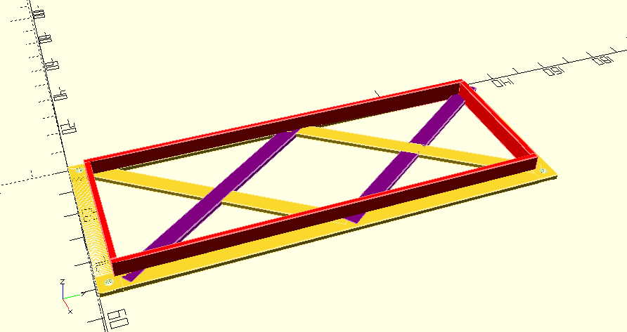
Bracing Frame
The actual part has conical locating dowels on the underside. These have been omitted, so that the piece will sit flat on a print-bed, and to make it easier to fit. |
|
|||
|
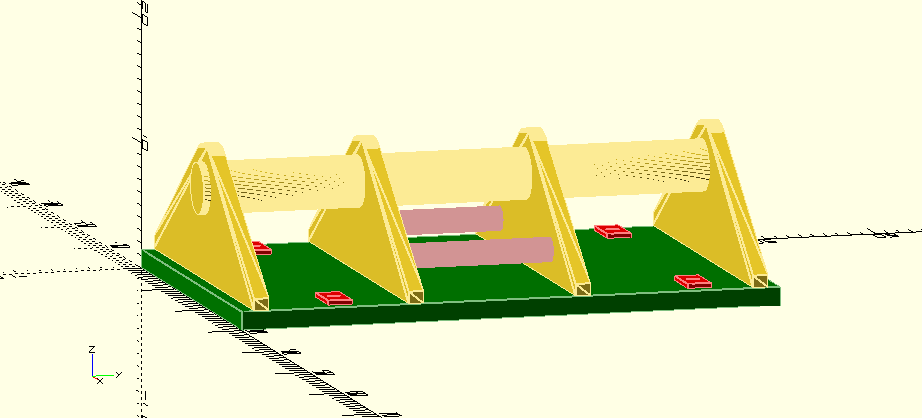
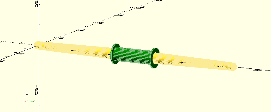
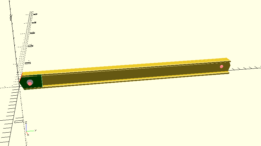
Bailey Bridge Carrying Bar
Shared between two men, to support Panels or Transoms or Base-plates. The real thing is a turned & shaped oak bar, with a metal collar. The latter, of course, is painted green to make it as easy as possible to lose. |
|
|||
|
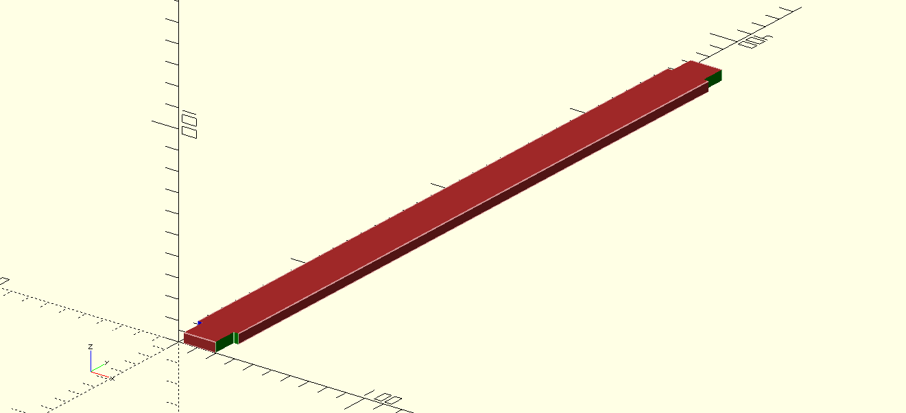
Chess / Chesses for the original "Standard Bailey Bridge"
Wooden planks that form the top surface of some bridge versions. The length varies according to the version. The thickness and notching also depends on the bridge version. Consider printing one as a template, and shaping actual real wood pieces to match. |
|
|||
|
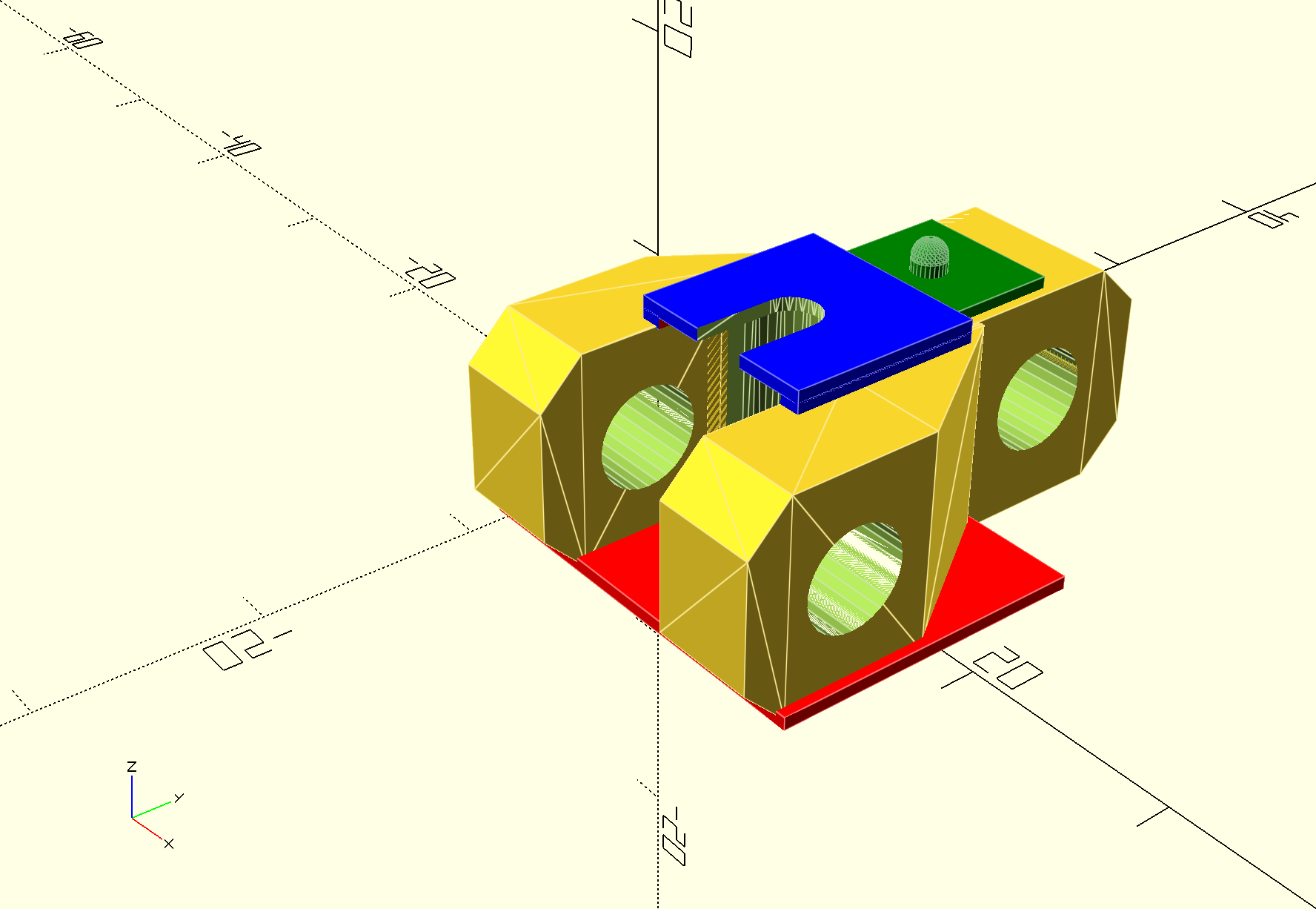
Mk2 Launching Link
Full Model. This piece is inserted between two panels, at the bottom, in order to create a slight upward angle for the launching nose. |
|
|||
|
Mk2 Launching Link
Top (Transom) Plate removed for easier printing - cut and fit a piece of plastic to fit. |
||||
|
Standard Bailey Bridge Panel Parts:
End-lug, male end/version. |
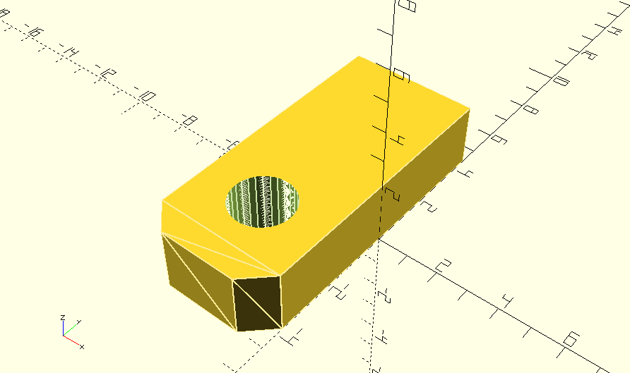
|
|||
|
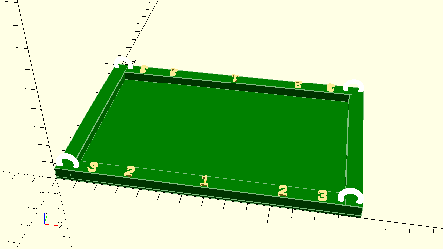
Standard Bailey Bridge Panel Construction jig
Holes to match exact location of Panel Pins - use a suitable small nail or other pin to ensure that built-up panels match each other. |
|
|||
|
Standard Bailey Bridge Panel Construction jig
Pins to match exact location of Panel Pins, to ensure that built-up panels match each other. |
|
|||
|
Standard Bailey Bridge Panel Parts:
I- and C-Section beams with re-inforcing and piercings in correct positions. |
||||
|
Standard Bailey Bridge Panel Parts:
End-lug, male end/version. |
|
|||
|
Standard Bailey Bridge Panel Parts:
Middle section of standard panel. To be sandwiched between outer sections (top & bottom chords.) |
||||
|
Standard Bailey Bridge Panel Parts:
Top and bottom sets of connectors, on a sprue to ensure correct spacing. Fits between the inner and outer, top and bottom chords (the horizontal lengths of C-Section.) |
Upper Sets
Lower Sets |
|||
|
Standard Bailey Bridge Panel Parts:
Single connector block / bracing-frame attachment point. |

|
|||
|
Bailey Bridge 'Original'; Standard-Widened; M1; M2; EWBB. Raker - connects the end of the transom to a panel, near to the top. |
|
|||
|
Bailey Bridge 'Original'; Standard-Widened; M1; M2; EWBB. Raker - split in half longitudanally for easier printing. Print two, then glue them together back-to-back, with the connectors at opposite ends. |
||||
|
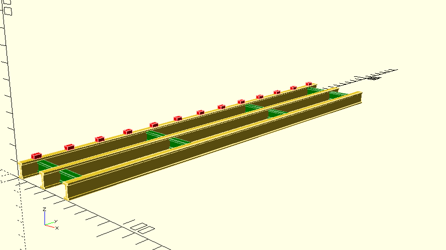
Button Stringer
These sit either side of the roadway, where the buttons (a) locate the chesses and prevent them moving (b) provide attachment points for the kerbing. |
|
|||
|
Bailey Bridge 'Original'; Standard-Widened; M1; M2; EWBB. Standard Stringer - no 'buttons' - for the centre of the roadway. |
|
|||
|
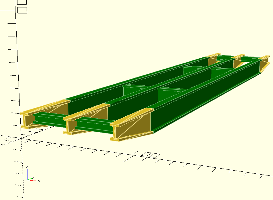
Standard/Plain Ramp
These form the main central portion of the roadway, at the ends of the bridge. Both types of ramp are similar to the respective type of stringer, but slightly thicker and stronger, with slightly tapered ends. |
|
|||
|
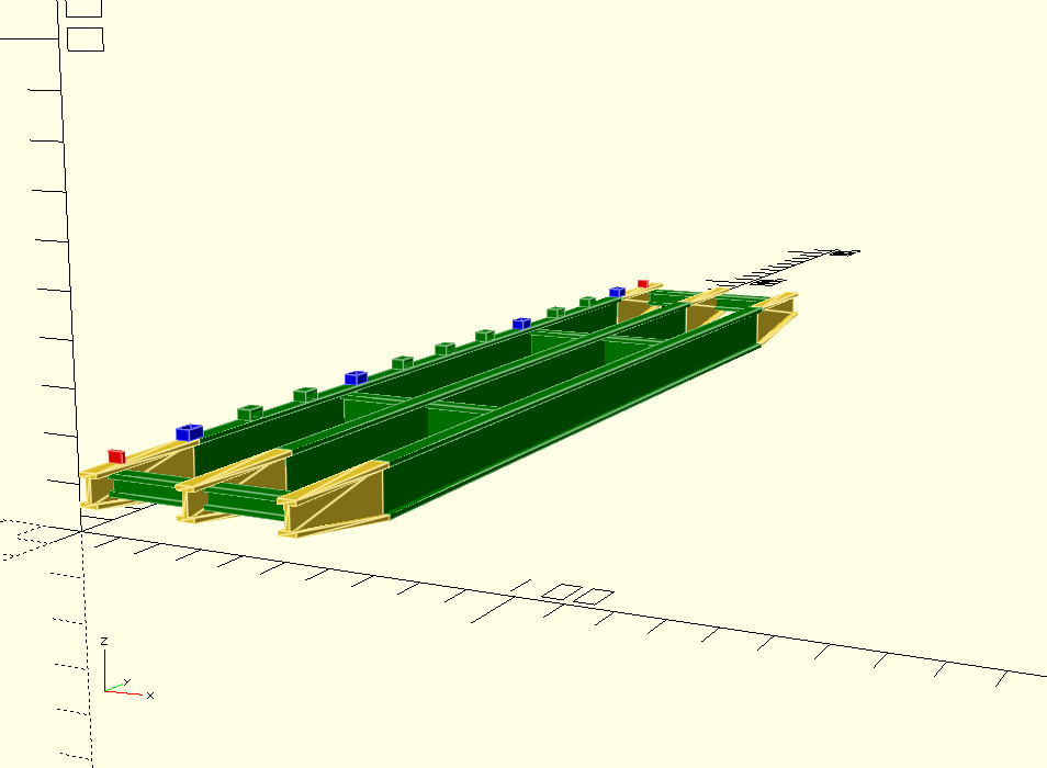
Button Ramp
These sit either side of the roadway, where the buttons (a) locate the chesses and prevent them moving (b) provide attachment points for the kerbing. Both types of ramp are similar to the respective type of stringer, but slightly thicker and stronger, with slightly tapered ends. |
|
|||
|
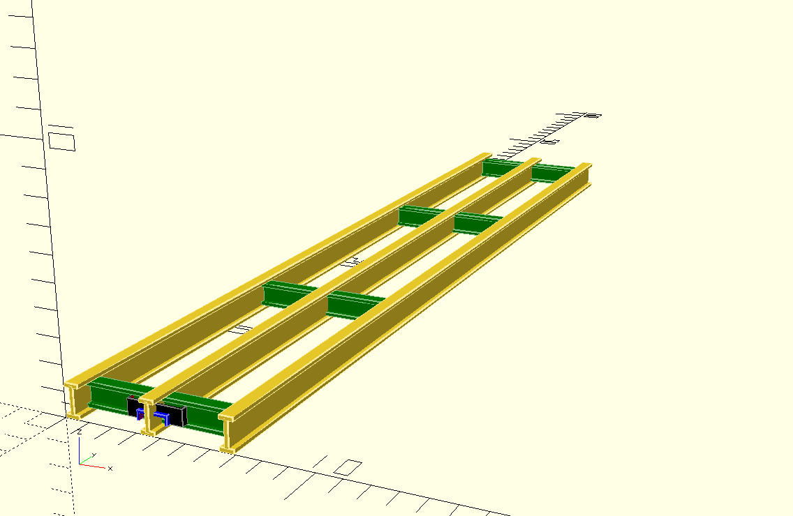
Bailey Bridge 'Original'; Standard-Widened; M1; M2; EWBB. Stringer - split in half (top vs bottom) for easier printing. Top and bottom are identical. |
||||
|
Bailey Bridge 'Original'; Standard-Widened; M1; M2; EWBB. Buttons to convert a standard stringer into a button stringer. Remove the sprue AFTER fitting, as it ensures correct spacing. |
||||
|
Original / Standard Bailey Bridge Transom
This is the shortest transom, for the narrowest roadway. |
|
|||
|
Bailey Bridge
Transom to fit American M2 bridges. Slightly longer than the original design, but otherwise very similar. |
|
|||
|
Standard Bailey Bridge Transom
Split into sections for printing within the limits of average-sized printers; And/or split down the middle of the main web, to avoid over-hangs. (To be glued back-to-back.) |
Lateral Sections
Top Web, raker attachment points, stringer locating lugs
Split along main web - print two and glue them back-to-back. |